How to build your own LagBox
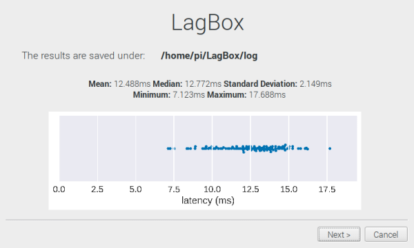
This guide will teach you how to build the hardware for your own LagBox, install all necessary software and conduct your own measurements on input devices of your choice.
More information on the project can be found here.
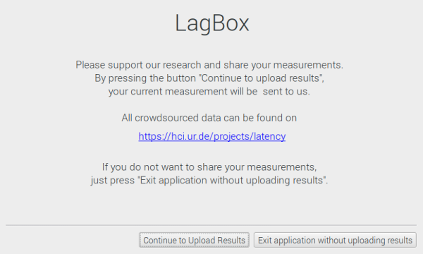
If you already have conducted measurements, you can share them with us here.
Hardware build guide
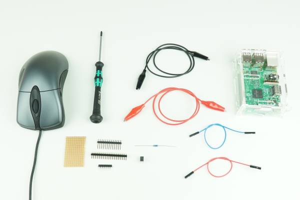
- Raspberry Pi computer (e.g. Raspberry Pi Model 3B)
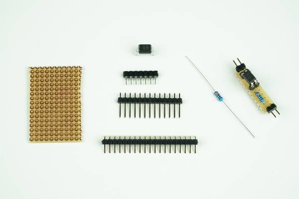
- optocoupler, model no. A817 (Link to datasheet)
- 150 ohm resistor
- perfboard
- male pin headers
- jumper wires
- crocodile clips
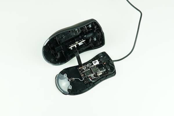
- An input device you want to use for your measurements (e.g. a mouse)
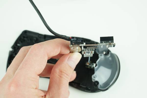
- tools to open your input device (screwdriver, etc.)
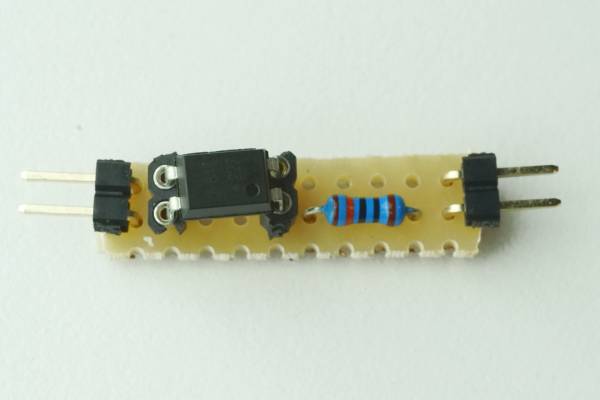
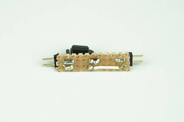
- solder sockets for the Optocoupler IC to the perfboard.
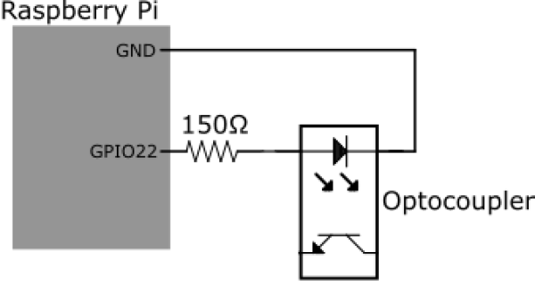
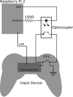
- connect one pin of the LED side of the Optocoupler to a protective resistor (150 Ohm).
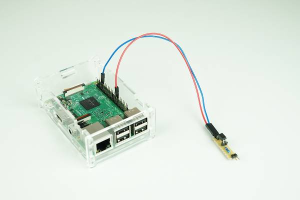
- add pin headers to both the LED side and the transistor side of the Optocoupler so both can be connected using jumper wires.
Make sure the Optocoupler is placed in the correct way in the socket (see datasheet).
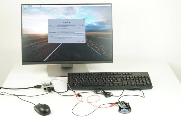
- connect the Raspberry Pi to a monitor
- attach a keyboard and a mouse to the Raspberry Pi (you will need a dedicated mouse for in order to control the software. Therefore you will need a second mouse if you want to measure the input latency of a mouse as shown in the image)
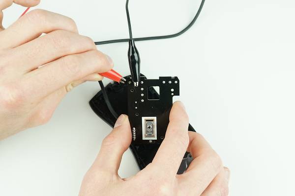
- connect the device you want to use for your measurements to the optocoupler as shown in the schematic
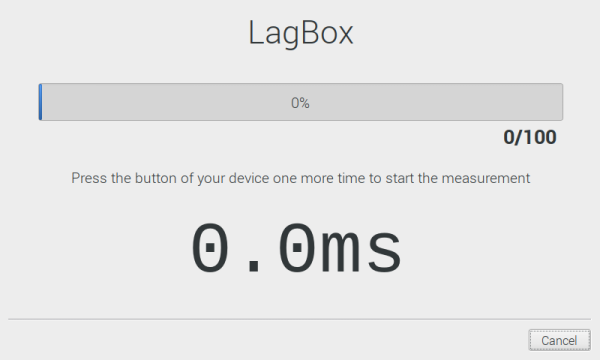
- start the LagBox software on your Raspberry Pi and you are ready to go! A guide on how to install the software can be found in the section below
How to install the Software
1. Install the latest version of Raspbian on your Raspberry Pi
2. Open a terminal
3. Install all dependencies available in Raspbian (PyQt5, Matplotlib, Seaborn):
sudo apt install python3-pyqt5 python3-matplotlib python3-seaborn
4. Install the evdev module for Python via pip (it's not available as a Raspbian package):
pip3 install evdev
5. Clone the code from the LagBox GitHub Repository to a folder of your choice:
git clone https://github.com/PDA-UR/LagBox.git
6. Navigate to the src/ folder inside the LagBox folder you downloaded (e.g. cd LagBox/src/). Run the following command:
make
How to use the software
- Open a terminal
- Navigate to the folder where you installed the software, e.g. …/LagBox/
- Navigate to the gui/ folder (e.g.
cd LagBox/gui/) - Start the software with the following command:
python3 latency_gui.py
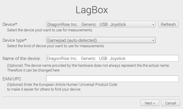
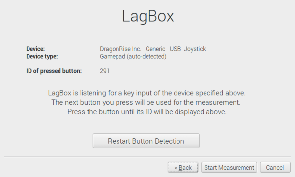
- Select the device you want to use for measurements from the dropdown. All devices connected via USB will be listed here.
- The correct device type will be preselected, but can be changed manually.
- Name the device to make the output log clearly attributable
- (Optional) Provide the European Article Number (EAN)/ Universal Product Code of the device. This makes sure that the device can be easy identified by other people
