Sketchable Interaction: Introduction and Terminology (2019-04-24)
tagged with: sketchable_interaction
Sketchable Interaction
Abstract
Compared to physical workspaces, digital workspaces allow little customization for end-users. We present Sketchable Interaction, a direct-manipulation environment that allows end-users to define and modify custom ad-hoc user interfaces, workspaces and workflows that fit their preferences and requirements. Sketchable Interaction is based on four primitives: * Users can create interactive regions by sketching. * The regions apply effects to other intersecting regions. * Regions can be linked to other regions or other digital or physical artifacts.
Within sketchable interaction, a small set of generic region effects allows for building a variety of workflows and user interfaces. As a concrete example, a user might sketch a simple document management workflow by drawing a region that shows a preview of files dragged onto it, drawing another region that deletes files, and attaching a tag as 'to do' effect to a tangible stamp widget.
Motivation
Sketchable Interaction (SI) aims to enable end-users to build ad-hoc user interfaces for workflows and workspaces.
Inspiration
Isenberg et al.'s Buffer Framework[1] inspired SI from the technical point of view. It targets large displays, such as multi-touch tables and augmented desks or walls. They propose to outfit interactive surfaces with underlying layers of buffers which rasterize the complete screen into equally sized squares with pixels being the smallest possible peculiarity. Once objects are moved around the screen each buffer applies its effect to the object according to its location on the grid. Such effects, however, only modify the graphical representation of an object in regard to its location on the interactive surface and buffer grid. Underlying information is untouched. For example, file icons or images can be seamlessly magnified in this way by moving them across a buffer which is modelled to allow a gradual increase in magnification.
Isenberg et al. extended on this concept by proposing further applications and usages of the Buffer Framework in regard to mobile spatial tools [2]. They defined tools for either swiping an area clear of objects, pile them together or change their alignment either in order to face the user or to be perpendicular to the screen. They achieved this by attaching buffers to tools, which are either moved around, e.g. via touch, and apply their action locally and instantaneously or change the underlying buffer composition by overwriting its values with the ones of the tool's buffer.
SI builds upon the Buffer Framework [1] in two major ways: * allowing the arbitrary sketching of a buffer instead of a fixed grid * allowing the manipulation of data as well instead of focusing on graphical representations
Concept
Sketchable Interaction's core elements are interactive regions and their interplay. Every interaction is performed and every action is triggered with the involvement of interactive regions. Therefore, a SI environment or context is an interactive region serving as a canvas on which users are able to sketch other interactive regions. In order to make the most basic interaction with SI -sketching- work, interactive regions have to satisfy certain qualities: * interactive regions trigger effects when colliding with regard to their capabilities * interactive region can be linked to another region with regard to their capabilities
For realizing sketching within a SI context, an interactive region has to be linked to the mouse cursor or detected finger blob via the position capability (the interaction technique for linking also involves interactive regions of course). Now, the mouse cursor or finger can be seen as a brush for the canvas. In order to paint on a canvas, the brush has to collide with it. Moving the mouse cursor across the SI context region triggers numerous collisions allowing the sketching of shapes. In order to do so, the canvas region has the capability to receive color information from an colliding interactive region as long as the colliding regions satisfies the send color information capability. Therefore, the colliding mouse region applies its effect to the SI context region, ergo the SI context's area of collision with the brush region is colored according to the brush region's color data.
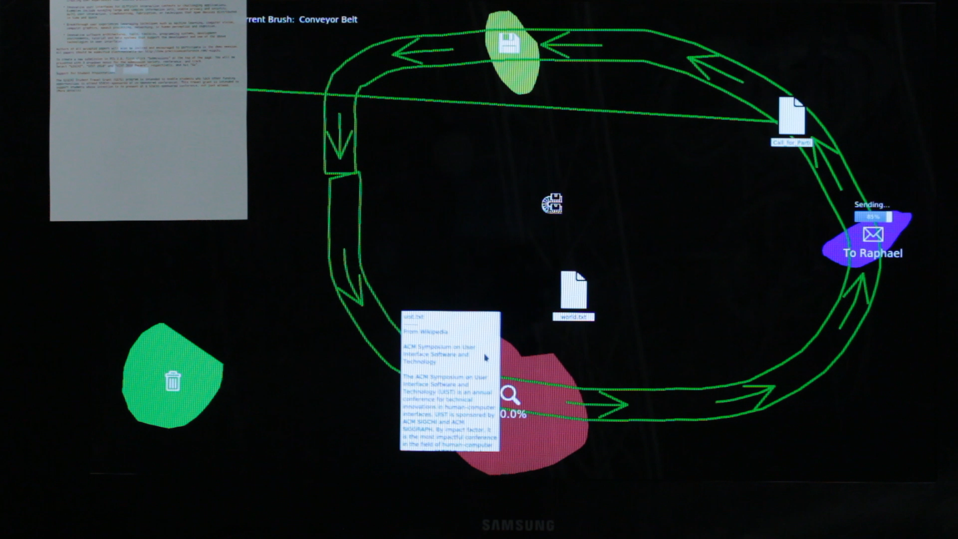
From here, users can sketch numerous interactive regions which are capable to send and receive a multitude of effects, so users can sketch their workspaces and workflows as they see fit. For example, a potential interactive region displays a seamless preview (read the content of a text-file or see the image stored in an image file) of a file on the desktop once the file's interactive region collides with it. Or for a more advanced example, users can build a workflow such as: Tag a file, compress it to zip and then send the zip-archive by email to another person.
Interactive Regions
In the previous sections some terminology in regard of SI has been mentioned which still needs definitions. With interactive regions being the core of SI, basically all of SI terminology revolves around interactive regions. The following sections provide these definitions while also including previously unmentioned SI terminology.
Collision
Colliding two interactive regions for triggering actions is one of the three fundamental concepts of interactive regions. As shown in the example in the previous section Concept, every interaction which users can perform with SI always requires interactive regions to collide, beginning from sketching other interactive regions, over assigning linking relationships or manipulation of data associated to an artifact a region is liked to.
Effect
Interactions occur once regions collide or are part of a user-defined process-graph. In order to trigger effects, region involved in the collision must satisfy the effect's capability requirement. Therefore, effects are a special kind of attributes which are unique for each class of interactive region. Attributes such as position and scale are present in every interactive region. If both regions are capable to handle effects (e.g. one is capable of emitting an effect, and the other, is capable of receiving that effect), the effects are applied to the regions. For example, moving a delete region into another region triggers the deletion effect which every region by default is capable of receiving. Therefore, the other region is deleted. However, the deletion effect is special, due to the fact that two deletion regions can intersect and it is not entirely intuitive to determine which region is to be deleted if not both. This is due to the fact, that every region must have the capability to be deleted. Here, SI checks the linking states of those regions. Therefore, a deletion region linked to a mouse courser or finger which is explicitly moved by a user will always delete the other colliding deletion region. Sketching a new deletion region so that it interects with another deletion region will always lead to the older one being deleted.
Capability
Capabilities describe whether effects are legal to be emitted or received by a specific type of region. Additionally, capabilities also describe whether regions can be linked via attributes. When regions interact and capabilities are satisfied, effect application or linking occurs.
SI aims to define a standard library set of capabilities. However, as can be seen in the section Expandability, new capabilities can be created and added to SI as a plugin.
(There will be a dedicated blog post on collisions, effects, capabilities in the future)
Process-Graph
A process-graph is the second fundamental concept of interactive regions. A process-graph is a user-defined sequence of regions which effects are chained in order to achieve a more complex goal beyond atomic regions. Therefore, regions are the nodes of a process-graph. Edges represent the connection between nodes and define the possible paths through the process-graph. These connections can be unidirectional or bidirectional.
Process-Graph Compression
SI performs Process-Graph Compression once a user wants to condense a set of sequenced regions -Process-Graph- into a single region called Compound Region. SI checks whether the selected graph can be compressed. (The underlying rules will be featured in a separate blog post, purely dedicated towards Process-Graphs and their compression)
Compound Region
A compound region is the result of process-graph compression. A compound region contains the sequence of effects of the originally sketched and then compressed process-graph. Therefore, it groups multiple regions forming a process-graph (or process-sub-graph) and represents this group as a single region. When put into the context of common programming languages, a compound region fills the role of a function or method, while atomic regions are lines of code.
(There will be a dedicated blog post on process-graphs, process-graph compression and compounds in the future)F
Link
Last but not least, the Linking of regions is the third concept and last fundamental concept of interactive regions and crucial for interacting with SI. Regions can be linked via attributes according to their capabilities. An interactive region either references an attribute or transfers it.
Attribute
An attribute is a property of an interactive region which can be linked to attributes of other interactive regions if capable either by referencing or transferring.
SI aims to define a standard library set of attributes. However, as can be seen in the section Expandability, new attributes can be created and added to SI as a plugin.
(There will be a dedicated blog post on linking and attributes in the future)
Atomic Region
An atomic region is a single region which exactly does one thing and only this one thing once colliding with another region with regard to capabilities. Therefore, it is a region generated via normal sketching. Its direct counterpart is a compound region, a region grouping multiple regions into one storing a sequence of effects to be applied once another region collides. In the context of common programming languages, atomic regions can be thought of lines of code.
Artifact
Artifact is the SI terminology for objects of any kind not originating from a SI context. Therefore, interactive regions can be seen as objects, however not as artifacts. Artifacs include digital objects like the mouse cursor, files, images as well as physical objects like fingers, tangibles, documents or sheets of paper.
SI aims to support the combination of digital and physical artifacts and their respective affordances in a context, in order to compose workflows (SI programs) capable of accepting various digital and physical artifacts as sources of data, input or output.
Expandability
The SI Runtime is designed (and still wil be designed) to support the following aspects: * new regions can be easily implemented and added as plugins * new capabilities can be easily defined and added to SI as plugins * new region attributes can be easily specified and added as plugins
References
- Tobias Isenberg, André Miede, and Sheelagh Carpendale. 2006. A buffer framework for supporting responsive interaction in information visualization interfaces. In Creating, Connecting and Collaborating through Computing, 2006. C5’06. The Fourth International Conference on, 262–269.
- Tobias Isenberg, Simon Nix, Martin Schwarz, André Miede, Stacey D Scott, and Sheelagh Carpendale. 2007. Mobile spatial tools for fluid interaction.