Sketchable Interaction: Core Interaction Concepts (2019-06-24)
tagged with: sketchable_interaction
Sketchable Interaction: Core Interaction Concepts
Sketching Mechanic
Description
Purpose
Functionality
Sketching Mechanic TL;DR
Collision Mechanic
Description
Within a SI context, the easiest form of triggering actions or effects is colliding two interactive regions. Effects are applied if the necessary capabilities match for the effects of the regions. For example, an icon of a PNG file is dragged around within the SI context where also an interactive region is located which triggers seamless previews of files as an effect. The icon has an interactive region linked to it which is capable of being affected by the seamless-preview-effect. Once the PNG file-icon collides with the previously mentioned interactive region, the content of that file are rendered and displayed to the user.
Purpose
The collision of regions is the most basic interaction of interactive regions within a SI context. Users deliberately trigger effects by colliding various interactive regions in order to manipulate artifacts, the contents of artifacts and generally changing the behaviour. When combining the ability to sketch new interactive regions with the ability to collide them, the minimum functionality a SI context has to provide is achieved. Therefore, these two SI primitives suffice to build working workspaces and workflows.
Functionality
By default, every interactive region can collide with every other interactive region within the same SI context. Based on the capabilities of the interactive regions which are part of the collision effects may be applied to the interactive regions themselves, the artifacts they are linked to or any other way of changing data or behaviour within a SI context. For example, the sketching mechanic entirely relies on collision in order to allow users to sketch interactive regions. A SI context foremost contains a canvas-region which is capable to receive the sketch effect. The mouse courser or detected finger blob both have an interactive region linked to them which is capable to emit the sketch effect. Then, users can draw interactive regions via the mouse or touch input due to them colliding with the canvas region which accepts the sketch effect. Therefore fills the pixels with colors where the collision takes place on the canvas.
Effect Application Rules
list of rules sorted based on what SI does first
Technical Challenge: Arbitrary Shape Collision
Collision Checking in General
With SI allowing users to freely sketch their workflows and workspaces, all kinds of arbitrary shapes can be drawn inside a SI context. Of course, arbitrary shapes could be mapped to a set of predefined common shapes like convex polygons (triangle, square, etc.), which facilitates collision problem immensly when compared to arbitrary shape collision detection. However, the output of the users then can no longer be seen as a sketch but more like a formal plan, defeating the idea that users doodle away within a SI context, iteratively modelling their workflows and workspaces as they see fit.
On the other hand though, this means that SI has to deal with the far more computational intensive collision checks for arbitrary shapes. Most notably here is the difficulty to check whether a point lies within a concave polygon. Of course, the concave polygon can be segmented into a set of convex polygon for easily determining whether a collision occured. However, there is a lot of overhead work to be done for that, in order to perform multiple convex polygon collision tests for one single concave polygon. That set of calculations has to be done in every update frame of the SI context (e.g. 60 frames per second) for every interative region which possibly can collide with any other interactive region within the SI context.
One way to reduce the amount arbitrary shape collision checks to a minimum is by testing whether collision occurred with the axis-aligned bounding boxes of the shapes first. Here, the simple check whether a point lies within a rectangle is performed. Then, it is only required to test the actual polygon if that AABB check succeeds.
SI Collision Checking System
The SI way of determining collisions, however, is different from the approaches above. The SI collision check system operates in three different stages of the overall SI context, region registration, region transform and region collision check. Region registration and region transform only serve preparation purposes for the actual region collision check.
Region registration
Once a region is fully sketched it gets registered within the SI context. From here, the collision system's first goal is to create a binary mask of that region. Therefore, each bit represents exactly one pixel. In other words, SI creates a binary image with the same dimensions as the SI context and initially sets all pixels to zero. SI then applies a Scanline algorithm for filling polygons with color. However, instead of filling a polygon with color, the Scanline-Algorithm reconstructs the newly sketched region within the binary image and sets every pixel which is part of the shape to the value one and leaves every other pixel at zero. Basically, the algorithm creates a list of pairs of intersection points of the scan line and the shape contour and then sets all pixels between the pair of points to 1.
Region Reconstruction Specifics
If a shape is convex there is exactly one pair of points per iteration of the scan line, but once a shape is concave it is possible to compute more pairs of points because of the way the edges of the contour of the shape continue. Therefore, there are pairs of points which have points between the two of them which are not part of the shape and require no filling. However, this problem can be easily solved by omitting each second pair of points.
Figure 1 shows an example contour of a shape which is concave and produces multiple pairs of intersection points once the scan line is applied.

As mentioned in the section about the Sketching Mechanic, SI always adds an edge after a user stopped the sketching process with the purpose of guaranteeing a closed shape. Therefore, there are always at least two intersecting points present per iteration of the application of the scan line which eliminates potential single line components of a shape (e.g. the character b would fulfill this characteristic). Going on from this premise, the pixels between the very first pair of intersecting points (X1 and X2) must lie within the shape. Then, the next pair features the end point of the previous pair as its start point. However, we know that the previous pair had to be filled, so the points which lie inbetween the current pair (X2 and X3) must lie outside of the shape, otherwise the pair would not exist at all or the pair would be e.g. X1 and X3. Then, the next pair (x3, X4) meets the requirements for filling the space between them, because X3 is a confirmed point on a edge of the shape such as X4. However the previous concave case can not repeat this way, which basically is the same reasoning as above but inversed. This whole precedure can be arbitrarily repeated.
Binary Mask Specifics
With each pixel being represented by exactly one bit in the binary mask, using common datatypes such as char, int, etc. wastes a lot of memory, e.g. 32 times as much memory in the case of the 32 bit integer datatype. In order to utilize memory to the fullest, SI implements a bit array, in order to store binary masks. The bit array is actually a 1D array created with C++'s std::bitset. Therefore, the bit array is an array with the length of image width times image height.
This requires far less memory than the naive approach for storing one int or even char for one actually needed bit. The following table highlights the differences of memory requirements for a resolution of 1920×1080 per mask.
| SI Bit Array | char Array | int32 Array | |
|---|---|---|---|
| Bits | 1920 * 1080 = 2073600 | 1920 * 1080 * 8 = 16588800 | 1920 * 1080 * 32 = 66355200 |
| Megabytes | 2073600 / 8 / 1024 / 1024 = 0.2471 | 16588800 / 8 / 1024 / 1024 = 1.9775 | 66355200 / 8 / 1024 / 1024 = 7.9191 |
Due to the use of std::bitset a single pixel or bit can be conviniently access via the common []-operator. The only thing to consider is that the binary mask, a 2D image, is stored in a 1D array. Therefore, indexing must be done via the common ways such as image width times y-coordinate of the pixel + x-coordinate of the pixel.
Region Transform
Region Transform occurs once a region is translated, rotated or scaled. In other words, regions are registered statically, therefore preserve their shape and position except when users modify these attributes. Then, the region enters a dynamic state and needs to be transformed according to the users wishes. Currently, SI handles region transformation equivalent to region registration, i.e. once a region's position, rotation or scale is changed, a new region of that type is basically created and then registered. Therefore, all computations for setting up actual region collision checking have to be repeated as long as the region is in the dynamic state.
Region Collision Check
Independend of an interactive region's state (static vs. dynamic), the collision system of SI utilizes that region's pre-computed binary mask for the actual collision test which result is crucial for triggering an action or not. Applying this naively, the test whether a pixel is within a shape or not is a lookup with O(1). Figure 2 illustrates this.

In order to reduce the number of pixel coordinates to test, in most cases only the pixels which form the contour of a shape are used to check whether it collides with another. Applied to a SI context, all present regions can be checked for collison simultaneously via a ray cast (green line) which is basically an orthogonal vector to all binary mask image plains running through all of the masks. Every intersection of the vector and the masks which yields a 1 is a confirmed collision with that particular mask and for 0 there is no collision with that mask. Figure 3 demonstrates this.

In most cases, regions only need to be tested once whether they collide or not which is sufficiently done by the aforementioned method. However there is a case, where a region is completely engulfed by another region. This may potentially lead to not registering the collision, due to checking if one of the bigger region's contour's points is set to 1 in the mask of the smaller, engulfed region which never is the case. Therefore, further checking is required. Naively, the SI collision checking system can test all regions with all remaining regions, creating some redundancy but also the necessary detail. Actually, SI omits all known collisions for the alternative testing run.
Therefore, the SI collision checking system determines collision relationships fast and handles the sequence of effects according to the regions' z value or in other words from top to bottom.
Collision Mechanic TL;DR
Linking Mechanic
Description
Within a SI context, two or more interactive regions can be linked via their attributes insofar they have the necessary capability for that.
For example, interactive region A is linked to region B via their positions.
Then, changing the value of the position attribute of B immediatly causes this change in region A as well and A is also moved according to B's position delta.
Therefore, both regions kept their original distance to each other, however they are found at a different position in the SI context.
Purpose
The linking of regions mechanic enables further dynamic use of interactive regions within a SI context. Returning to the example of the previous section, linking regions via the positional attribute enables user to mass move interactive regions by referencing all but one regions' position in another region. Additionally, the linking mechanic directly enables the use of physical artifacts in a SI context. For example, once a tangible is tracked by SI, its detected contour is this artifact's interactive region. However, such contour-based interactive regions often are blank and effectless regions requiring setting of a effect. Here, it is possible to transfer attributes from another region to the artifact's interactive region. Therefore, the physical artifact can assume the role of a rubber, by having a Deletion-Effect transferred to its interactive region.
Recap: Definition of Attribute
As seen in the previous blog post: LINK
An attribute is a property of an interactive region which can be linked to attributes of other interactive regions if capable either by *referencing* or *transferring*.

...
Additionally, effects are a special type of attribute, due to them being unique for each class of interactive region unlike position or scale attributes, which are present in every interactive region.
Functionality
Generally, each region can be linked to every other present region based on region attributes and corresponding region linking capabilities. An easy example for that is linking two regions in terms of their position attribute as shown in the previous sections. Moving one region in a direction immediately causes the linked region to be relatively (positional delta) moved in that direction as well. However, only regions sharing the capability to be linked via the 'position' property actually show this behaviour when linked and moved. Generally, this is the case for all kinds of possible linking capabilities and between regions.
In silang (a link to the silang blogpost will follow soon) linking is expressed as follows:
A -> B => property_of_A, property_of_B;  # unidirectional
A <-> B => property_of_A, property_of_B; # bidirectional

# short forms if property_of_A equals property_of_B
A -> B => property;
A <-> B => property;

# example with position property
A -> B => position;
The SI way to view such linking relationships is called Linking-Graph. Therefore, a linking-graph comprises two or more interactive regions which are linked in some way. Here, interactive regions represent nodes and the linking relationship between nodes represent edges. In terms of graph theory, linking-graphs are mixed graphs as they feature either directed or undirected links.
Directionality
Unidirectional Linking
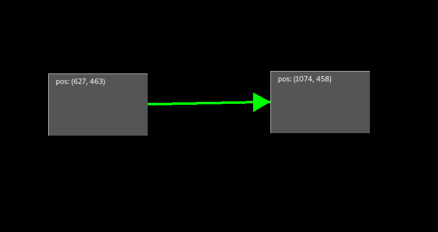
The easiest way to link regions is by establishing a unidirectional link. In terms of graph theory unidirectional links are directed edges between two nodes or interactive regions. Using the example from the previous sections again, regions A and B are unidirectionally linked according to their position attribute. In silang, this is expressed as:
A -> B => position, position; # or A -> B => position; for short
Therefore, moving B in a direction immediately causes A to move in that direction as well. But due to the link being unidirectional, moving A directly has no effect on B whatsoever.
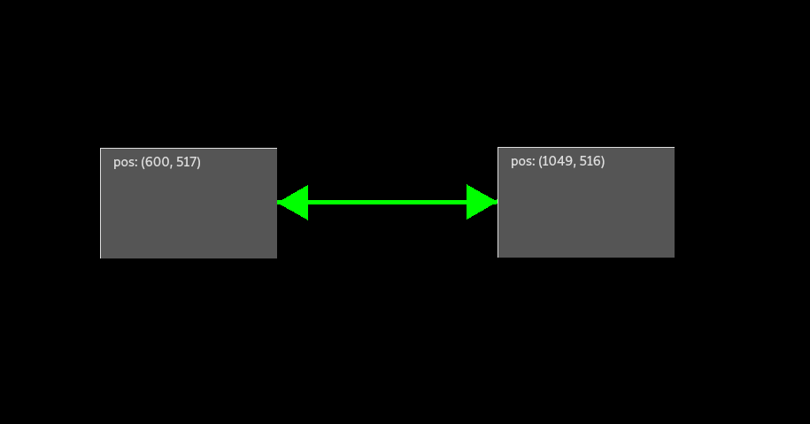
Bidirectional Linking
When expanding on the example in the previous section so that movement of A also triggers movement of B, then a bidirectional linking relationship is necessary.
In terms of graph theory this is equivalent to an undirected edge.
Therefore, A and B are bidirectionally linked according to their position parameter.
In silang, this is expressed as:
A <-> B => position, position; # or A <-> B => position for short
Now, both can be moved directly while the other is also moved due to the bidirectional link.
Cyclic Linking
The example in the section above already features the easiest form of a cyclic linking relationship, due to A's position changes affect B's position and vice versa.
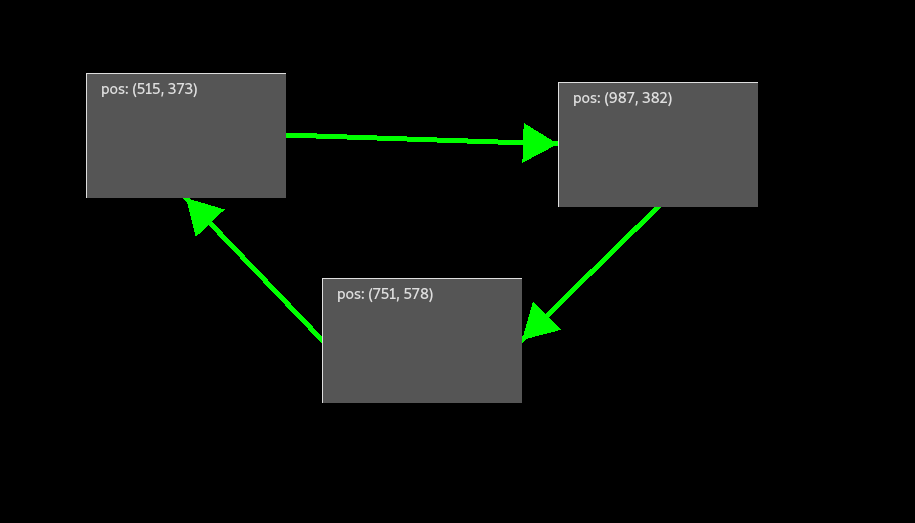
In order to showcase cyclic linking-graphs more intuitively, the example is expanded with a third region C and cyclically and unidirectionally linking it to A and A to B and B to C, forming a triangular shape.
Again, the position property of the regions is used.
In silang, this is expressed as follows this:
A -> B => position;
B -> C => position;
C -> A => position;
Referencing and Transferring of Attributes
In the current state of the concept of SI, interactive regions can be linked by either attribute referencing or attribute transferring.
Attribute Referencing
SI uses attribute referencing as default style of attribute linking for attributes which are present and always defined in every interactive region such as position, scale, color, etc., unlike e.g. effect. Attribute Referencing is similar to pass by value of common programming languages.
The directionality of the link determines which region stores the reference of the linked attributes. This is trivial for the bidirectional case, because both regions store the reference of the other.
For the unidirectional case (shown in silang):
A -> B => position;
A is linked to B via position. This means B receives the reference of A's position attribute. Therefore, changing the position of B results in A changing its position relatively as well. However, moving A does not affect B.
Attribute Transferring
Attribute Transferring is SI's default way of linking interactive region's effect attributes which are not necessarily always set within a SI context. Attribute Transfer is similar to pass by value of common programming languages'.
For the unidirectional case (shown in silang)
A -> B => DELETE;
the behaviour is equivalent to Attribute Referencing with the exception, that no reference is stored in region B. Instead, B deep-copies A's effect attribute and stores it by value. In this way, B's instance of the effect and A's instance of the effect are both unique. Therefore, changing A's effect attribute does not change B's effect attribute.
Technical Challenge: Infinite Recursion
When reviewing Figure 03 again, the most problematic technical challenge is easily visible: infinite recursion. Due to the cyclic nature of the linking relationship depicted in Figure 03, it does not matter which of the interactive regions is moved, in order to move all of them. However, they also never stop moving, due to said infinite recursion because A triggers movement of B which triggers movement in C which triggers movement in A again and so on. In order to solve this problem, SI uses universally unique identifiers (uuid). Therefore, every interaction with a set of linked regions is bound to an uuid which is generated by the interactive region which is directly affected by the user, called the entry region. The uuid is passed to the next region based on the linking relationship along other data (in the case of Figure 03: positional data). Once the action reaches a region which already processed the specific uuid, SI checks whether that region's linked property is equal to the one which originally left that region. When this is the case, the action is dropped by SI in order to prevent said infinite recursion.
Difference to Process-Graphs
While Linking-Graphs and Process-Graphs share some similarities such as them being depicted as graphs, entry region, they are mostly distinct concepts.
The major difference is that linking-graphs, unlike process-graphs, define no sequence because interactions trigger immediate actions affecting all regions of the linking-graph at the same time.
However, process-graphs need a specific, user-defined, sequence of effects which are applied to colliding artifacts in that specific order and process-graphs also work only with effects and no other potential region attribute.
Additionally, linking-graphs cannot be compressed, while process-graphs can be compressed for decomposition purposes of a SI context.
(A dedicated Blog Post for Process-Graphs follows soon)
Potential Interaction Techniques
Up until to the writing of this blog post, only little and superficial thinking in terms of interaction techniques for linking has been done. Generally, the questions which are currently unanswered are: * how do users want to link regions? * how does the selection process look like? * how does the deselection process look like? * how to correct potential mistakes? * how to provide undo? (timeline within SI context?; generally greater problem within SI) * how do users want to break links? * how to move a linking-graph as a unit? * etc.
Once SI reaches the maturity to be formally evaluated, these question are on of the first to be answered. Therefore, dedicated blog post about that will follow once answers are either found or had to be defined.
Linking Mechanic TL;DR
SI's linking mechanic is a powerful way of defining more advanced relationships between interactive regions. The SI way of thinking about linking relationships between multiple region is the linking-graph. Linking-graphs are a set of regions which are either unidirectionally or bidirectionally (and therefore cyclically) linked to each other according to the regions' attributes and capabilities. In order to prevent infinite recursion, a uuid is generated at the start of an interaction and each region in the linking-graph performs the action exactly once, ignoring actions of the same uuid.
Linking of regions comes in two modes: Attribute Referencing and Attribute Transfer. Attribute Referencing is similar to pass by value of common programming languages. It allows binding a reference of an attribute of region A (e.g. position) to an attribute of region B. Then changing this specific attribute of B triggers the change of attribute of A permanently. For example, linking regions A and B via the position attribute, moving A results in B moving relatively according to A's positional delta).
Attribute Transfer is similar to pass by value of common programming languages'. This method allows interactive regions to have attributes transferred to them, i.e. interactive regions can deep-copy other regions attributes according to their values. For example, regions C and D are about to be linked. D's effect attribute is currently not set (i.e. neutral when colliding with other regions) and is meant to assume the effect stored in C. Once, the link is established D stores a copy of C's effect attribute. Unlike Attribute Referencing, although C and D have the same effect attribute, none of the regions is referenced in the other, i.e. changing C's effect attribute does not change D's effect attribute and vice versa.